
How does charging and regen work?
Everything you wanted to know about battery charging and regen but were afraid to ask.
So we all know that we’re driving on electricity, but how does that work in terms of recharging the battery, and how does regen work?
Glad you asked! Let’s dig in!
A battery’s State Of Charge (SOC, 0-100%) is measured by a few factors, but primarily by voltage. The higher the voltage, the higher the SoC. As a battery is used, the voltage will drop, and the SoC decreases.
An oversimplified primer:
- Voltage is the amount of energy that an electron has, or how much it physically vibrates. This is measured in Volts.
- Current (or Amperage) is the rate of movement of electrons. One Coulomb is 6.25 x 10¹⁸ electrons. One Coulomb per second is One Amp.
- Resistance is measured in Ohms, and is a measurement of how much energy (volts) the electrons lose as they pass through a circuit. Applying one volt to a circuit with a one ohm resistance will cause the circuit to draw one amp of current. If the circuit had 10 ohms of resistance, however, only 0.1 amps of current would be drawn. Volts = Current x Resistance. Current is marked by I in equations (from the French intensité du courant), so we see V=IR.
- Power is measured in Watts – and one Watt is (basically) One Volt at One Amp for One Second. Remembering that I is for current, the equation is P=VI. This is the total amount of overall energy available during one second, a combination of how much movement each electron has, and how many electrons are moving.
- Energy is measured in Watt-hours (or kilowatt-hours), and is Power measured over an hour. So One Watt, for One Hour is One Watt-Hour, or Wh. Fifty-seven thousand watts for one hour is 57 kWh (the energy capacity of our battery).
- For any given circuit (including when recharging a battery), you have a source of electricity with a given voltage. You apply that to a circuit, and depending on the resistance of the circuit, a current will be drawn.
Now that we have the primer out of the way, let’s get into more details on how charging works!
A battery will have a voltage which can be measured with a voltmeter. If the battery is not in a circuit (or otherwise nothing is drawing power from the battery), this is called the Open Circuit Voltage, or OCV.
In order to recharge a battery, you must apply voltage to it. Now, remember that voltage is how excited the electrons are. If you apply the same voltage to the battery as its OCV, nothing will happen. The electrons that you have are with the same amount of energy as the electrons in the battery, so nothing will happen. However, if your electrons are more excited, they will push into the battery, causing electrons to move (which as we know, is a current). So, applying a voltage higher than the battery’s OCV will cause it to draw current. This charges the battery.
Now a battery at a given state of charge will have a certain resistance. Remember that V=IR, or rearranged, I = V/R. So 5 volts with 2 ohms of resistance will draw 2.5 amps of current. 10 volts will draw 5 amps.
Thus, the larger the voltage difference between your applied voltage and the OCV, the more current the battery will draw and the quicker the battery will take charge.
Because the OCV will rise as you charge the battery, if you want to keep the battery charging at a fixed current, you must continuously raise the voltage applied as charging progresses. This phase of recharging is called CC – constant current.
Unfortunately, at about two-thirds of a full charge, your battery will reach its maximum safe voltage that can be applied to it without causing damage. So at this point onward, the amount of current that the battery will draw for recharging will gradually taper down naturally. This phase of recharging is called CV – constant voltage.
You may see battery recharging referred to as CC-CV because of this.
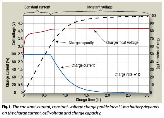
In the above example, notice that after about 40 minutes the battery has reached around 2/3rds capacity, but yet charging isn’t complete until long after 2 hours! So as the battery gets more charged, the rate at which you can increase the state of charge drops off considerably.
For some reason, GM decided to artificially limit the current when the battery charged, drastically cutting down the current.

The Bolt can take a maximum of 150A of current, although this is only available if your charging station provides more than 50kW of power. Most 50kW stations are limited to 125A, and some are limited to 100A.
At around 55%, the Bolt will cut the maximum charge power down to 60A. Around 68% it will cut it down to 40A, and around 86% it will cut it down to 25A. Finally 10A at around 94%. These percentages can fluctuate a little based on a few factors, including the battery temperature. They are actually based on voltages – 370, 380, 390 and 400V. So up until 370V, the Bolt will charge at 150A – 370 * 150 = 55.5kW maximum, or 370 * 125 = 46.2kW maximum if at an older 50kW station. Then 100A as soon as it tapers down, so 370V * 100 = 37kW. This will increase to 380V or 38kW before tapering down to 380V * 60A = 22.8kW, then increase to 390V * 60A = 23.4kW, etc.
That is why we see the power drawn increase over time.
However, GM changed everything in 2020, and they introduced a larger battery and removed this artificial taper:
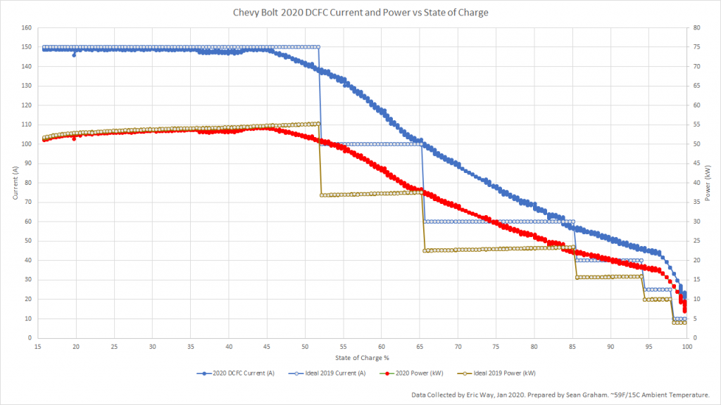
In the above image, you can see the 2020 details (solid colours) and 2017-2019 (hollow circles). Blue is current and on the left vertical axis, Orange is power and on the right vertical axis).
Needless to say, without the artificial taper, it will charge faster as more power is drawn.
Ok, enough about charging – what about regen?
Simply put, anything that generates power does so by using a magnet to force electrons through a circuit. This increases the electrons’ energy (voltage) through something similar to friction.
Think of it this way. When you rub your hands together a lot, you generate heat through friction. This is because heat is energy, and physically moving something through resistance increases its energy, as kinetic energy through movement is transferred into the electrons or atoms in the object.
This is an oversimplification, but sufficient for our explanation.
Every electron has a magnetic field, and they can be pushed around by using an external magnetic field – a fixed magnet. So if you rotate a magnet through a coil of wire (which has resistance), you will force the electrons through the wire, through the resistance, and they will gain energy (voltage) as a result! That’s how a generator works.
Similarly, if you apply voltage to that coil of wire, the magnetic field can push a fixed magnet and cause it to rotate – that’s a motor! In fact, most motors are called motor generators for that reason – they can do both.
So, when you are using regen in your vehicle, the physical movement of the car is rotating a magnet in the motor/generator, which will increase the voltage of the electrons by providing a resistive force (reducing the movement of the car). This energy transferred to the electrons (voltage) is then applied to the battery, and the battery will draw current and reduce the voltage of the electrons. They pass through the motor/generator again, gaining voltage, slowing down the car a little more, and the cycle continues.
So regen really is just the same as stationary charging the battery! Except instead of grid power, the energy comes from the movement of the vehicle.
Ok, so what’s up with the regen limit then?
So just like when recharging, if the system is already at your battery applied voltage limit, it cannot be raised above that without damaging the battery. This means that the amount of current drawn will be less than when full, which means less resistive force is applied to slow down the vehicle. But it doesn’t mean that the battery is full, it just means that you can’t draw enough current to suit the deceleration needs that we have, and we have to use the friction brakes.
Another way to look at it – let’s say that your battery is a bucket, and you push it down into a full bathtub so that the bucket rests on the bottom. Water will pour in really quickly at first, but as the water level in the tub decreases, the amount pouring in will slow down until there’s only a thin stream coming over the edges. Eventually the water level in the tub will match the height of the bucket and filling will stop, even if the bucket isn’t full yet.
But wait, how can the car control the rate of regen?
What a great question!
Here’s basically how the car works:
Motor/Generator <–> SPIM <–> Battery
(there’s a high voltage distribution block in there but that’s irrelevant to this discussion)
The SPIM (Single Power Inverter Module) switches power between Direct Current (DC – battery side) and 3-phase Alternating Current (AC – motor side). Simply put, if you apply a positive voltage to a circuit, the electrons will move around in the same direction and return back to you. This is called Direct Current. If, however, you switch the voltage between positive and negative, the electrons will travel in one direction through the circuit, then reverse direction. This is called Alternating Current. AC switches direction forward and backward multiple times a second at a given frequency (called Hertz, or Hz). For household power, in North America we typically have 60Hz (switches direction forward and backward 60 times per second). For cars, it’s different – but also mostly irrelevant to our discussion. Just know that converting from DC to AC is called Inverting, and that’s where the SPIM gets its name from.
Getting back to the point – if a vehicle is moving at a given speed, how can we control how much regeneration we have?
You may have seen exhibits like this at your local science center, but if not imagine this: you have a large wheel with a hand crank (or perhaps a bicycle), and a few old incandescent lights that you can turn on and off with some switches. Crank the wheel with no lights on and it takes a little bit to get up to speed, at which point it’s easy to keep turning (voltage is created but no current draw = no additional resistance other than normal friction). Turn a light on and suddenly you can feel that it’s harder to keep the wheel spinning. Turn 2 lights on and it’s harder still. 3 lights on and it’s really hard to keep the wheel turning, and it starts to slow down.
Or, look at it another way – get the wheel spinning as quickly as you can and let go. It may take 60 seconds to fully stop with no lights on, 20 seconds to stop with 1 light on, 10 seconds to stop with 2 lights on and 5 seconds to stop with all 3 lights on.
Increasing resistance due to added load = more force required = more slowdown. So if you can control the amount of load (current drawn) then you can control the amount of resistance, or force required, or slowdown. I can control the load based on the number of lights that I turn on, but what if I only have 1 light?
So instead, let’s put an automatic switch that turns the light on/off with a given frequency. If the switch has a 50% duty cycle (for example, turns on and off once per second) then the resistance will be halved, and will require half of the force, so the wheel will slow down half as quickly. If the duty cycle is 25% (on for one second, off for 3), then I require 1/4 the force. Unfortunately we’re going to see the light flicker as it goes from off to full brightness once per second.
Instead of once per second, however, what if I do that 100 times per second, or 100,000 times per second? Instead of seeing it flicker, I’ll just see it at about half brightness with a 50% duty cycle. At 25% duty cycle, the brightness will still appear constant, but at 1/4 the brightness as full.
This is what our SPIM does during regen through the use of something called MOSFETs (fancy electronically controlled switches). There’s a bunch of other complicated stuff, but that’s the main relevant part.
The force is the kinetic energy of the vehicle. The car monitors the power output of regen, and tells the SPIM to control the duty cycle so that the battery draws the exact amount of current (and thus power) that it wants, causing the vehicle to decelerate at a controlled rate!
Pingback: Chevy Bolt – Most Frequently Asked Questions – All EV Info