Chevy Bolt EV Battery Disassembly and Charging Limitations
Summary
Questions about the slow charging rate of the Bolt (compared to other cars) come up quite often. While the charging port being limited to 150A is often blamed, this is not the root cause. I firmly believe that the pack design (and not the cells) provides a very limited way of removing heat. If the pack were to be charged any faster, it could create unacceptable temperature gradients in the cells, which could cause severe degradation.
To understand why, let’s dig in to see the pack design and learn why the thermal management is barely adequate.
The battery design
The Chevy Bolt battery is built with 288 lithium-ion nickel manganese cobalt (NMC) cells that have a peak voltage of 4.167V, a nominal voltage of 3.65V, and a capacity of ~55Ah each for the original N2.1 cells, and ~60Ah for the newer N2.2 cells. The battery is formed by welding together packs of 3 cells in parallel, and then putting 96 of those three-packs in series. This configuration is called 3P96S. The pack voltage, thus, peaks at 4.167V * 96 = 400.04V at 165Ah (N2.1) / 180Ah (N2.2), giving a total of ~60kWh / ~66kWh usable.
These three-packs of cells are put into modules. Eight of the modules contain ten three-packs, and the other two contain eight three-packs. The modules are put into 5 rows, with the larger modules along the bottom, and the two smaller modules on the top under the rear seat.
The battery itself
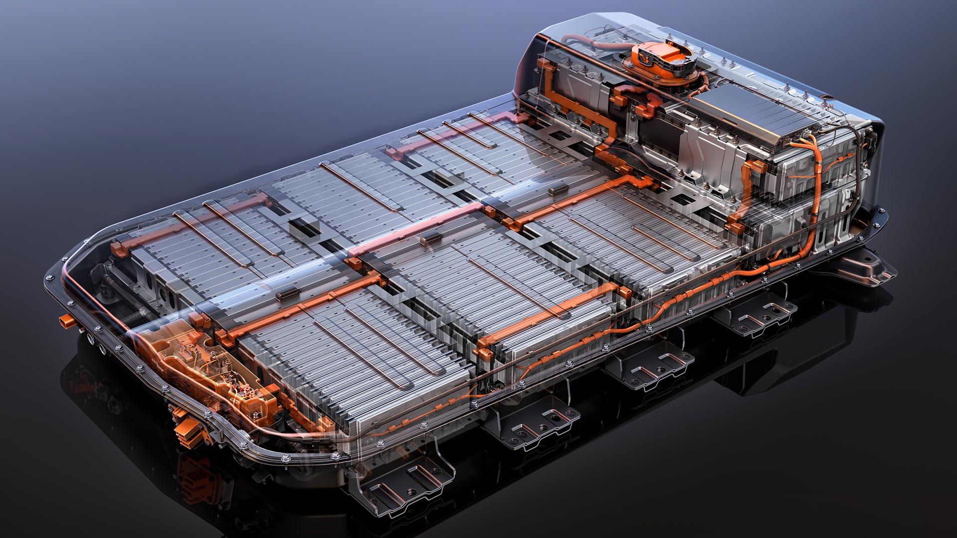
Here’s what the battery pack looks like with the cover off:

The battery is composed of 10 modules doubled up in 5 rows. There are 4 rows on the bottom, and one on top under the rear seat. These modules are bolted together lengthwise in other to keep the cells under moderate pressure. In the above picture you can see two of the modules with space for a third one that was removed. This is looking towards the “front” of the car / pack.
Beneath the modules is the thermal plate which is where the coolant circulates, and the thermal transfer pads that link the aluminum heatsinks to the thermal plate can be seen as the beige pads above. Those are similar to thermal paste used for your CPU heatsink; metal on metal has very bad thermal transfer properties as there winds up being very little contact at a microscopic level. To have proper thermal transfer, you need a paste or a very easily deformable thin and conductive pad to ensure proper contact between the two.
Here is a closer view of a module:

Here’s looking at the side of a module, ripped out:

The black plastic is made of multiple repeating pieces, better seen in the image below. Remember that we have 3-packs of cells. So 3 adjacent cells together have their tabs spot-welded together with a copper busbar that links to the next 3-pack. The center busbar above is cut and facing towards the camera. We had to do this because you can’t remove the cells from the plastic frame otherwise. The bottom circuit board runs along the modules and is used for the cell-pack voltage measurements.
Here’s what it looks like when you rip a module apart:

You can see the (three) aluminum heatsinks and an exposed cell at the bottom.
Taking out the black plastic and re-stacking them to see a bit better, you can see the black foam pad between the cells, and that one aluminum heatsink/bracket runs between two cells. That foam pad allows the cells to expand/contract slightly while keeping the cells pressed tightly together. The holes in the aluminum heatsink would clip over tabs in the plastic holders.

another view

Below I took the top aluminum bracket/heatsink off so you can see the length of the cell, the foam pad between the cells, while still having the bottom bracket for reference

top shot:

Here’s an annotated end-on view showing the components stacked:

In the above photo, you can see the thin plate that runs between the top two cells (call them 1 and 2) with the foam between cells 2 and 3. Cell 3 has the plate on the bottom of it and the next cell would be under that. This plate is about 11″ long, and made of aluminum – which is not fantastic for heat conduction. With only 1 1/8″ width in contact with the thermal plate, this means that in total there is about 12.4 square inches in contact with the main thermal plate for every 2 cells. This is a very small amount.
If you imagine the coolant plate on the left side of the image above, think about how the heat transfer would occur. The right, foam side of the cells above is furthest from the heat exchanger plate at the left. That will remain the hottest during charging, with a temperature gradient towards the left of the cell and the thermal plate.
Degradation increases exponentially with heat. This effect is less of a concern if the entire cell heats up or degrades uniformly as the degradation will be uniform. But when you have a gradient, you will get different levels of degradation at different spots inside the cell, which is a big problem. Degradation of the cell increases the resistance, which means that more heat is generated as time goes on, further increasing the rate of degradation. In extreme cases, this can cause enough heat to cause a fire.
In Conclusion
This heatsink and thermal plate interface design is the major limiting factor in both charging and conditioning. This limitation is observable directly via the coolant vs pack temperature. The coolant will quickly cool or heat up and then have to be throttled while the pack takes a long time to catch up. This is also why we’re so throttled charging in hot temperatures. In those conditions, you’ll see the coolant drop about 10-15C below the pack temp, and then the A/C throttles way down and the pack slowly cools down. There’s more heat exchange capability from the external side, it’s limited internally to the pack.
I believe this is why the Bolt’s conditioning is so slow. You can’t push it any faster without having temperature gradients in the cell, which will destroy it relatively quickly due to uneven wear within the cell. This also severely limits the fast charging speed. Even if you could double the power of the battery heater or the A/C, the problem isn’t there. The coolant already quickly changes temperature, but it takes a while for it to get into the cell and equalize.
How could it be made better?
GM could have added a top thermal interface plate, which would have more than doubled the heat exchange capabilities. Since temperature conduction is proportional to the difference in temperatures, it actually has a squared effect. You’d probably have 3-4x the amount of equalization and exchange ability by doing that, and it would have been a relatively simple change in the battery design.
Also, the aluminum that GM uses is only 0.04″ thick. Increasing this by 50% to 0.06″ would have very little pack design impact, but increase the heat transfer rate which would incrementally improve the temperature equalization.
“The pack voltage, thus, peaks at 4.167V * 96 = 400.04V at 165Ah (N2.1) / 180Ah (N2.2), giving a total of ~60kWh / ~66kWh usable.”
I have a 2020 Bolt that received a new battery in Dec 2021. It’s labeled as a LI-MM-C.F. B2.0.1 64kWh. I’m guessing it has cells at 55ah. Can you confirm?
Also, I’m presuming you’re factoring the results of your formula by approximately 90% to determine the usuable kWh for the two battery chemistry designs.
400v * 165ah = 66,000ah or 66kWh
The usable is 60kWh or 90.9%
400v * 180ah = 72,000ah or 72kWh
The usable is 66kWh or 91.7%.
It seems that there is plenty of confusion surrounding the batteries, but you’ve done a great job in making things clearer!
In 2017 I met one of the Chevy Bolt developers in Germany on his fast charger test route through Europe. He told me that they had to decide if the car can charge faster but has less range and is more expensive due to better cooling or if they limit it to 150A, which was sufficient a decade ago when the development started. Because 10yrs ago there were no chargers available with more than 125A. Even in 2017 there were only a few worldwide. When the Bolt started, it was already really expensive. Yes, it has its limitations. But somewhere a developer has to decide to not do something to limit the price.